
What documents do I need to build my project?
A Construction Drawings package is required to build a project. This is a comprehensive collection of documents that contains all the pieces that show the technical solution of the build, along with drawings that go into detail about assembly, lists of materials, and site information among others.
A Construction Drawings (CD) package starts with very general information and slowly goes into very detailed specifications. The information shown here is primarily aimed at residential design, but it is mostly the same for every project, with additions based on typology. A standard CD set contains the following components:
Project cover and notes: general information about the project.
Site plans: general plans that show the positioning of the building on the site.
Foundation plans: Foundation placement and dimensions.
Floor plans: individual plans of each floor with dimensions, wall structure, floor finishes, and furniture placement.
Roof plans: a plan of the roof with dimensions and slope information.
Elevations: 2D projection of each building elevation, containing information about finishes, doors, windows, floor, and element levels.
Sections: a cut through the building, showing wall, floor, and roof structures, floor, and element levels.
Framing plans: not always provided by the architect, these plans show how the floor structure of the upper levels is laid out.
Stair details: a detailed section through the staircase showing dimensions and levels.
Railing details: a detailed elevation of the railing with dimensions.
Detail plans: larger scale plans of certain key areas, such as the kitchen or bathrooms, containing detailed dimensions of individual component placement.
Interior elevations: go together with the detailed plans, showing level dimensions and component information for the bathroom and kitchen.
Construction details: Blow out of certain areas of the building in high scales (1:10, 1:5, or 1-1/2’’=1’-0’’, 1’’=1’-0’) showing detailed component information and layers.
Door and window schedule: A complete list of all doors and windows along with their IDs, dimensions, and information.
Framing schedule: not always provided by the architect and only for certain building structures, contains every element used in the framing of the building, along with dimensions and information.
Material bill of quantity: complete list of all the materials and what quantity is needed for each (in either square or cubic meters or feet).
Material specifications: shows the general look of all finishes.
Electrical layout plan: position and connection of all lighting fixtures, sockets, and switches.
Electrical schedule: a detailed list of all electrical elements.
HVAC layout plan: position of all HVAC components.
HVAC schedule: a detailed list of all HVAC elements.
Plumbing layout plan: position and connections of all plumbing components are not always provided.
It’s important to note that irrespective of the scale of the project, this package is standard. Some pieces depend on the project type (for example the framing plans are not provided by the architect in the case of a concrete structure) while others depend on the complexity of the project (plumbing plans are not provided for very simple projects). To showcase all of these elements, we will use the Cabin House 4.1 and Contemporary Estate projects.
Project cover and notes


This contains general information about the CD set: a cover for the set, a notes page, and a drawing index that shows all the sheets, their title, and size.
Site plan
The site plan shows the position of the proposed building in relation to the lot, as well as any natural elements and how they are tackled.
The site plan is drafted based on the survey and topographic map, which have to be provided prior to design work commencing. These are carried out by surveyors and show the lot dimensions, area, topography levels, and site elements (such as trees). Because of the required information, it is not possible to start design work without it.
Foundation plan


The foundation plan shows the layout and dimensions placement of the foundation. This is designed to show where the foundation goes and it ties into both the overall structure and the structural axis.
The structural axis shows the loadbearing layout of the design. A line indicates a loadbearing beam and an intersection indicates a load-bearing column. Structural axis are mostly used in concrete and steel structures, less so in wooden framing
Floor and roof plans


Floor plans are a fundamental piece of the package and contain the most information out of all the drawings. They give a general picture on where everything goes and additional information:
Wall structure and layers.
Detailed interior and exterior dimensions.
Door and window information, such as dimensions and ID.
Room information, such as ID, surface, perimeter, and finish.
For the roof plan only, slope direction and angle.
Elevations


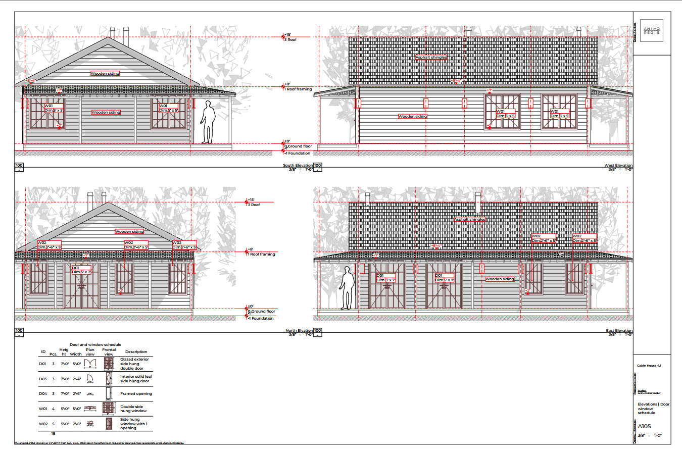
Elevations are 2D projections of each side of the building that is visible. The show building enclosure information, such as:
Door and window IDs and dimensions
Floor level and height dimensions
Exterior finish information
Relationship to any adjacent building
Sections


Sections are 2D cutaways through the building that show structural layering information, as well as how the floors, roof, and site interact with one another. Normally, at least 2 sections are drafted (a long section and a cross-section), but more may be added depending on the complexity of the project. After the plans, they are the second most valuable drawings, offering essential information on how to build the design:
How the floor is layered (structural composition and finish)
How the walls are layered (interior finish, structure, insulation, and exterior finish)
How the ground floor slab works (slab on grade, basement, etc)
How the roof sits and what is it made of
How the building sits in relationship to the site
Where the details are located
Framing plans


Framing plans show of the roof structure is layed out, complete with dimensions and placement of each roof framing element. In certain projects, roof framing plans are also drafted to show the framing of the floor between levels (only in the case of wooden frame structure buildings) or for the flooring finish (for example in the case of floating floors). But for the most part, roof framing plans are the most common drawings.
Stair and railing details

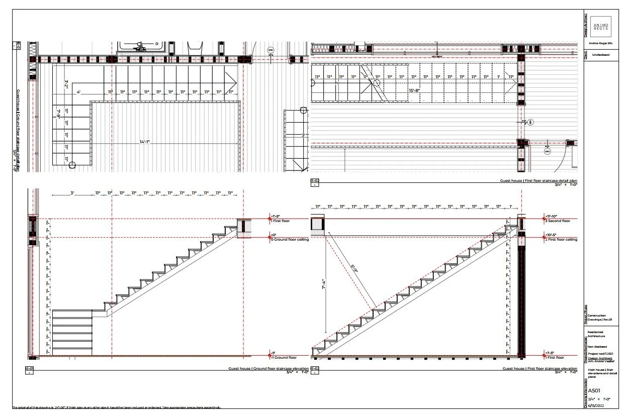
Stair details are a section through the vertical access that shows the layout and dimensions, with both general dimensions as well as level dimensions. They show how access is done, what is the height and width of a step, and the general design. The same also stands for railing details, showing the dimensions, height, and general design of the railing.
Because vertical access is a key component, being of importance to both fire security legislation as well as an accessibility issue, staircases are highly regulated (both in their dimensions and in their design, for example, it is not possible to evacuate a building through a main circular staircase) and the stair detail might also even be required as part of the building permit process in certain legislations.
Detail plans and interior elevations


Detail plans take certain parts of the plan and scale them further, showing more in-depth dimensions and placement of certain fixtures or cabinetry. They are usually provided for the kitchen (as part of the kitchen design, which also included kitchen interior elevations) and the bathroom (that also have their own additional interior elevations) designs.
Interior elevations, in the same manner, are scaled-up views of parts of the interior, most often the kitchen and bathrooms, but they can also be provided for other areas as well, where additional information is necessary.
For the kitchen they show general and level dimensions, cabinet type, placement of fixtures (sink, dishwasher, etc), finish information and cabinet type.
For the bathroom they show level dimensions, finish information and placement of fixtrures.
Construction details


Construction details show key parts of the building at very high scales, representing in detail the components and layers that go into the construction. After the plans and sections, they are the third fundamental component of design, showing exactly how the project is built. They are generally 2 types of construction details: general details and in-depth details.
General details show only the essential information (materials type, general information, and fitting), while in-depth details show much more information (dimensions, exact material information with supplier, assembly information on fitting, etc). If the construction solution is standard, then a general detail will suffice. However, if the solution is more complex or even custom, then in-depth details will be required. For most projects, general details will be used.
Door and window schedule
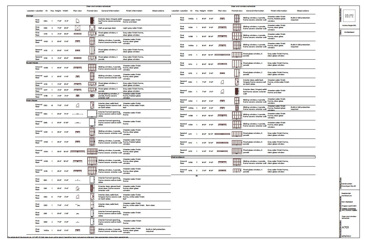

The door and window schedule is a detailed list of all doors (both interior and exterior) and windows used in the project complete with the follwoing information:
ID, so that the door or window in the list can be identified on the plans and elevation
Dimensions, width and height
Front and plan views, showing the opening direction
Genaral information, such as type of door leaf, window typology, opening type, etc
Finish information
Bill of quantity and specifications
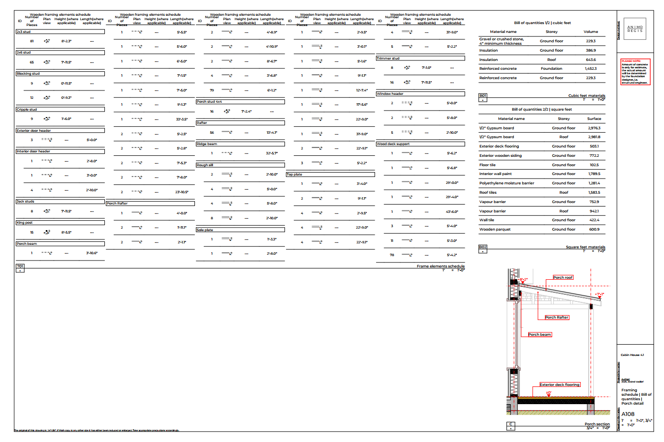
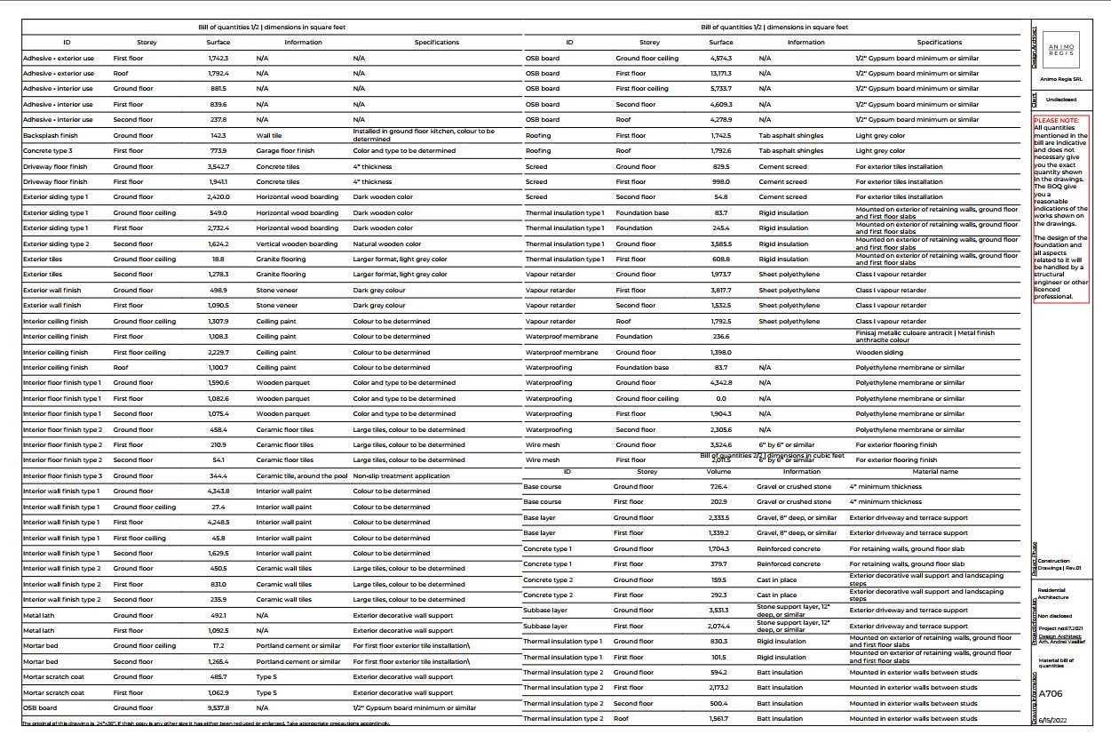

The bill of quantity is a complete list of all materials used in the project along with calculations for each amount that will be required (expressed in square or cubic meters or feet, depending on the project location). The material specifications are 3D cutaways of the building that show how each material should look along with other information.
The bill of quantity is essential to pricing a project, as it shows the exact amount needed for purchase to build. Bill of quantities can be provided for the general materials, but in some cases, they are also provided for additional components, such as the wooden frame (a complete list with all framing elements, their section, and length) or certain special finishes (for example, how many linear feet or meters of the plinth are required).
Material specifications show the type of finish of each material used, using both images and written information. The goal of this document is to make the project more budget scalable, where if a certain material can’t be found or is cost prohibitive, then it can be replaced with something that looks similar and still works in the design. This situation comes up often, especially for new build projects, where things can change on site.
Electrical and HVAC layout and schedule


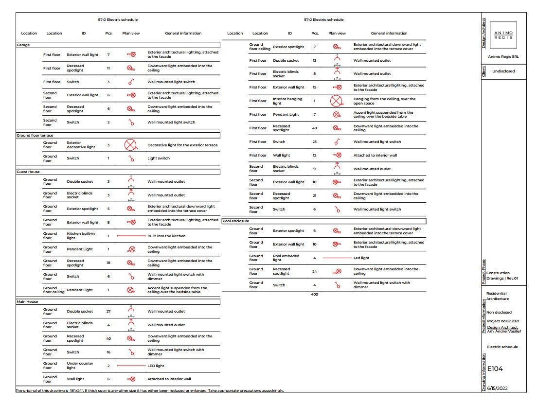
Electrical plans show the layout of all the lighting fixtures, switches, electrical installations and sockets, along with information for each and how it’s connected.
The electrical schedule is a list of all electrical elements from the plan, that shows the information on all of them, such as type, finish, and placement.
The HVAC plans and schedule show the same information, structured in the same way, but for the HVAC components, such as radiators, ventilation elements, air conditioners, etc.
The plans for both will always show both interior and exterior elements.
Please note that these plans only show the layout and list, a separate specialist (such as an electrician or HVAC engineer) will be required to do the calculation and create the final design based on the provided layout.